DIY Sheet metal Rolling Brake Table
Based on the concepts of a sheet metal brake or folding table, it’s modified so it rolls the sheet metal around a larger die to create a large radius bend.
A typical folding table brake has an upper die foot that typically has a pretty sharp front, which can create a very sharp inside radius. By shifting it back, you can vary the radius a little bit. However, to make a large radius on thicker sheet metal is pretty tough, and even if you can, the results aren’t very smooth and nice.
Here’s a decent picture I found of a sheet metal bend by a folding table:

Image Source: google
I did a lot of searching on the internet, and most of the large radius tooling is for a press brake, and expensive! Since I don’t have a press brake, and the tooling was expensive, I kept looking.
I finally found something similar to what I was thinking, and based on that, I came up with this version.
It is kind of a cross between a folding table and a tubing bender.
The upper jaw tooling is replaced with a large radius chunk of shaft, supported at the ends, and then the side arms rotate on the center of that upper jaw, and use another chunk of shaft as the lower mandrel to roll the sheet metal around the stationary tooling.
Many years ago I had made a small folding table, so I had a decent starting point to work with.
I had two major radii I needed to accurately bend: 1″ radius and 2″ radius.
I had a chunk of scrap steel I had bought at the salvage steel place, it was 3.5″ in diameter, and just over 17″ long. That was perfect, as my widest bend was just over 12″, and the folding table I had was just over 20″ wide.
I first chucked that large piece in the lathe, and drilled and tapped 1/2-13 holes in each end so I could thread in a bolt or threaded rod.
Then I did the same thing on some 3/4″ diameter rod. After that, I found some 2″x1/2″ flat stock, about 36″ long and drilled some holes in the end and a pattern of holes away from the end to use for the bending arms.

My first setup with it was to set the large diameter roller on top of the sheetmetal, just in front of the old upper jaw, and then put the arms on each side hanging down, and then bolted the lower shaft in place. Like this:


However, it just didn’t work quite right. I needed to have that upper jaw tooling held down in place, as when I tried to lift on the arms and rotate the leaf tooling around the upper tooling, it just wanted to lift off.
So I needed some way of holding the upper tooling down to the folding table frame. I came up with these angles to hold the upper tooling in the right place, and they clamp to the frame that I had already.

That was the ticket! As you can see, it worked quite nicely to make the first large radius rolled bend!
I also found that placement of the lower shaft actually worked better if it was down a bit more, which gives a bit more leverage when rolling the sheetmetal around the bend.
Here’s some action shots of making the large radius bend:


I found that the 3/4″ rod was a little bit weak for the leaf tooling, so if you are making one for yourself, use 1″ shaft for that. What happens is that it likes to flex a bit, whereas a larger shaft won’t do that. I backed up the 3/4″ shaft with a piece of thick wall tube, and that helped quite a bit, as well as providing some roller action.
This method worked really well, and the bends that it made were really consistent and no tooling marks either. It was so much easier than the first method I tried, which was hammering the sheet metal over a piece of shaft. No comparison in time, effort and final result! Here’s a picture comparing before tooling (left), and after tooling (right)!

Here’s a few more pictures of bending:


As you can see, the wrap around piece for the fuel tank gets pretty complicated in shape!
For bends of even larger radius, like 6″ and 12″, I just put the piece of metal in, and then hand bent it around the upper tooling. That way I was able to incrementally bend it, and have good control.
So what are these weird looking shapes that I was bending??
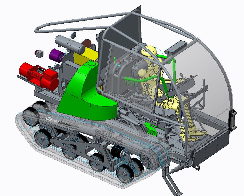
Well, they are for the fuel tanks for the All Terrain Track Chair project I’m making to provide mobility to a client confined to a wheelchair. Click on the link for more information about that project.
Here’s a few overview shots of the fuel tank fabrication:


And now here’s the flat pieces that I had laser cut for me:

Then some in progress shots, followed by TIG welding them together:
I also have a youtube video of these fuel tanks.


