Man Basket w/ Boom Extension for Knuckle boom crane
See the knuckle boom crane page for more information about putting a knuckle boom crane onto a 1951 Int’l truck. 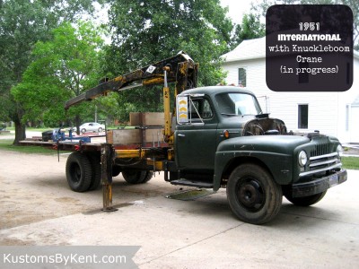
Right from the beginning when I started the knuckle boom crane project, I had envisioned making a man basket attachment with a longer boom so that I can reach some higher places for maintenance or new construction. I have rented a man lift before, and the one available locally is not real well maintained, not always available and is a bit of a pain to rent. I’ve rented another one that’s nicer, but it’s 45 miles away, more expensive to rent, plus gas for the truck to go get it and return it, plus the time wasted. So having one available whenever I need it on a piece of equipment I already have, well, that seems like a no-brainer! I did some early research, and found that this is not a hair-brained idea on my part, that these are commercially available and regularly used on knuckle boom cranes, and other straight boom cranes. One company that does a business of making these baskets is Diversified Products. Here’s a nice picture of what I want to make:  Source: http://www.diversifiedproduct.com/products/man-baskets/single-man/
Here’s another link with a few more options: http://www.diversifiedproduct.com//wp-content/uploads/2011/04/Man-Basket-Trifold-Brochure-8.5-x-11.pdf
I have no idea how their products rank, and it doesn’t really matter since I not buying one, I’m making one. I can say from reviewing through their site and their documentation that they seem to know what they’re doing, and seem like a decent resource to reference. I’ll only be using this for myself, it won’t be used commercially, so I have very limited liability. I plan to fully test it with test weights before any human being gets lifted more than a few feet off the ground, as safety is key in this project. Since my brother was coming out after the New Year for a few days, I figured this would be a good project for him to help me with.
So Jan 4-7 2015 we got after it!!! We started with a paper sketch:

I was throwing around a few different concepts for attaching the extension boom onto the existing boom, and none of them were completely feeling like a winner. After some brainstorming with my identical twin brother, he proposed a different concept that sounded like a winner. A bit more discussion, some cardboard CAD to check feasibility, a sharpie drawing on the steel table, and that’s the idea we decided to go with. A bit of scrounging in the shop yielded the steel we needed to make it happen, and that area was settled. Since my brother had come up with that concept, I put him in charge of executing it. That left me free to focus on the basket portion of the assembly. Here’s the Sharpie CAD on the steel table: 
After reviewing the steel on hand, I revised my man basket design slightly, and here’s what I decided to do: 
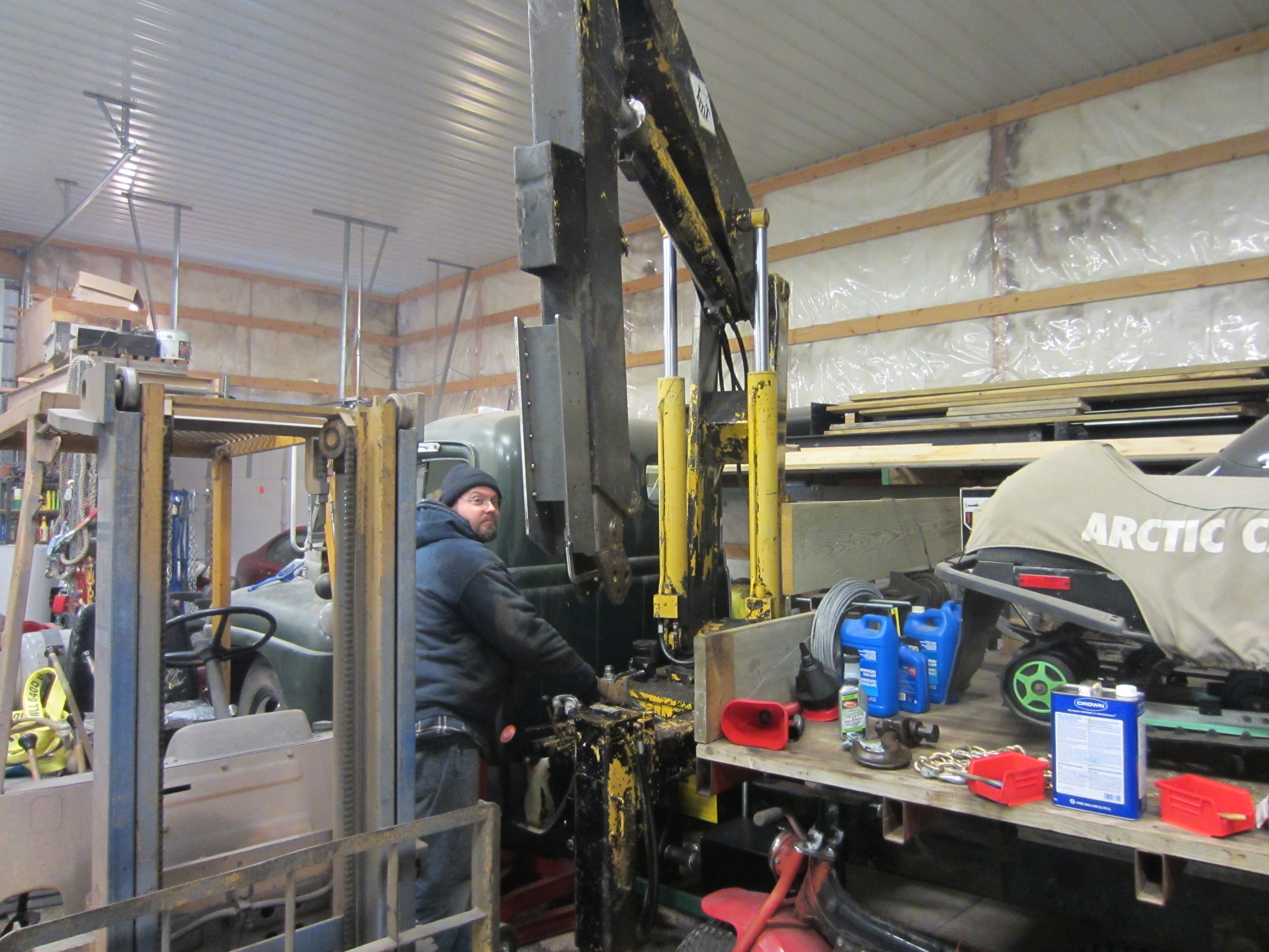
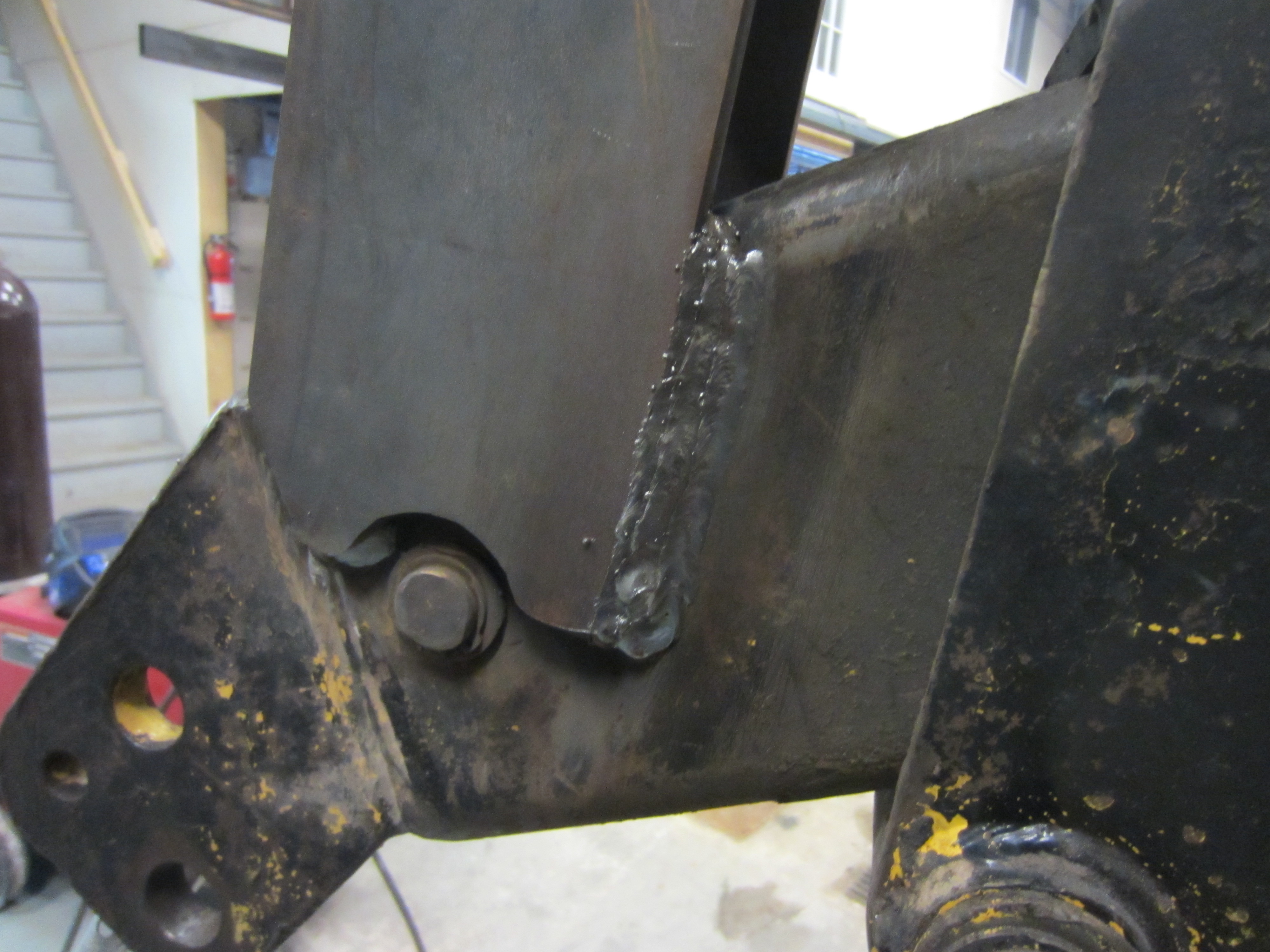
With that, we both got to work cutting steel for our respective parts. First some progress shots of the boom attachment feature, showing it tack welded together, and then clamped in place so that we could cycle the knuckle boom closed and back open to check for possible interference.


This has 5/16″ thick side plates, with 1/4″ thick top/bottom plates. The blue tube is just there for spacing it all together during tack welding.


This design will allow the extra boom extension to slide up along the top of the boom, and allowing it to always be carried with the crane. It will be manually extended, and locked in place with a pin.
Meanwhile, I was making some progress on the man basket itself:


See the Tube Bender page for more information on that piece of equipment. Back to the boom attachment, further progress was being made on that, my brother showing his handywork: 


So at this point the side plates are welded onto the main boom, but the boxed section for the tube is not welded on. So we tack welded that in place, and then slide in an 8′ section of 4″ square tube, 1/4″ wall thickness. Now to cycle the knuckle boom again to check for clearances before we fully weld it.


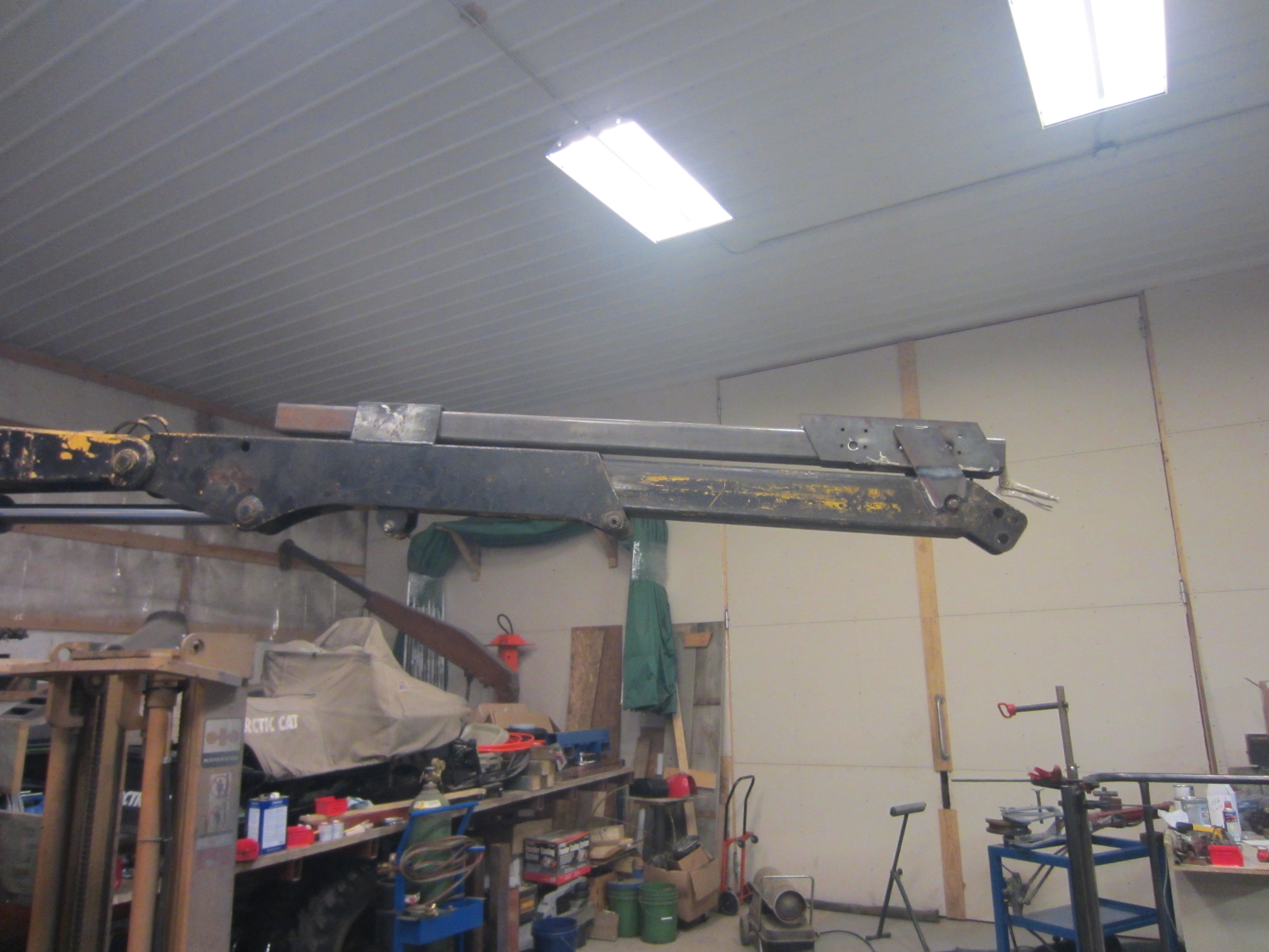
That worked well, so now the boxed section can be fully welded to the main boom.
Here’s a few pics of the crane hydraulic extension boomed out and back in, with the manual extension pushed in, in the storage position.
Now back to work on the man basket end. I was working on the yoke that allows the man basket to pivot and connects to the end of the boom. I started out by making the yoke large enough that the man basket could be rotated 90 degrees for storage, and not be limited in any way when up working. That meant the arms of the yoke were quite long, almost 6′!
Here’s some pics of drilling the pivot holes in the 2×3″ tubing that’s the arms of the yoke. These will pin onto the man basket pivots with 1″ pins.


Next we spent some significant time figuring out how we wanted to attach the yoke to the end of the boom, and be a quick-tach connection, with limited slop, and use the materials we had on hand.
We ended up with a design that uses two 1″ pins, some heavy angle and plates so it is picked by the angle on top of the boom into one top pin, and then locked in position by the bottom pin.
Here’s our paper sketch before I moved over to the mill to drill the 1″ holes for the pins.

After milling the plates, we tack welded the angles onto the end of the boom, and then we clamped everything together with yoke and the quick-tach to the end of the boom to tack it all together.


Once that was done, we disconnected it from the boom so I could swing the boom around and set the outriggers all the way out. Then we connected it back up to the man basket to see how it all looked.
Here’s some shots of connecting it, which should show pretty good how that works:


Now for the money shot, does it work???


Yup, it does! And this is with only tack welds! However, we weren’t happy with the spring in the yoke portion. The torque tube is too small, and the yoke arms are too long, resulting in a lot of bounce. Does it hold the weight of a 230+ lb man? Yes, but not confidently. This was a good test to do, particularly since the entire yoke was only tack welded together.
Unfortunately, my brother had to head back to PA, so I was back to working by myself from here on out.
The current yoke uses a piece of 2×3″ 1/4″ wall tubing as the torque tube, and it’s just not quite enough. Coupled with the 6′ long yokes, and it just not a good choice.
After a bit of evaluation, I decided to cut the yoke apart, upgrade the torque tube to be 3×3 x 1/4″, and shorten the yoke arms from 6′ to 3′. This also significantly decreases the torque load applied to the torque tube. So as much as I dislike doing rework, it’s the right choice to make, and fortunately only tack welds to cut apart.
After cutting loose the tack welds, knocking loose the gussets, I was able to cut down the yoke arms to be much shorter, then I cut a new piece of 3×3″ tube for the torque tube, and then made some outside plates to tie the torque tube to the arms better. Then I tack welded it all back together in preparation for another test.


Now to see how it all works with the revised yoke assembly! This time I have the hydraulic extension all the way out, and the manual extension all the way out. Total length from centerline of crane to centerline of man basket pivot is 24.5′!


I was starting to run short on time at the shop, and I knew I wasn’t going to finish it, but I wanted to do a load test on it. I gathered together some drop lengths of tube, and weighted the whole mess on my steel scale and was able to come up with 222 lbs of steel. That’s good enough for a quick test, so I loaded up the man basket with it.

That seemed to perform pretty good. Much less spring and bounce, and with the torque arm much closer, it doesn’t feel like you’ll be hanging out in mid air as much.
That’s all the time I had, so now I needed to park it until next time, so I retracted the manual boom, and then cleared a spot up on the bed for it reside, and then rotated it up into position.


I did lower it to just a few inches above the bed for storage, but the above pics are better for showing the unit.
Items I have left to finish, and will have to be finished in June/July 2015:
1. Fully weld the man basket assembly, and add grating and kickers, and a swinging door
2. Drill some 1″ holes in the 4″ square tube to pin it in position
3. Create a chamfered end to the 4″ tube so that it retracts better through piece already on the boom
4. Add a brake mechanism on the man basket to yoke to lock it into position so it doesn’t swing when trying to work out of it.
5. Add safety loops on the yoke for tie off points for a safety harness (note: I already have a safety harness)
6. Perform complete load test to determine the safe working load.
7. Paint entire assembly
Here’s some math behind where I’ll be at for capacity.
First, here’s a chart of the capacity, plotting horizontal reach and lift rating:

From there, I was able to get the equation of the trendline between positions 2 to 5, (y = -397.35x + 10562) and knowing that the horizontal reach from crane center line out to the pivot point on the man basket to be 24.5′, then the approximate lifting capacity at the pivot point is ~826lbs. So I’ll need to subtract off the weight of the man basket, and then that will be my absolute max weight that I can have in the basket. I’m going to derate that number too, to leave a bit of a safety factor.
Calculations are all well and good, but before anyone gets lifted more than a foot off the ground, I’m going to verify this using steel test weight, and then rotate/lift through the full range of motion while monitoring everything.
